Beam Load Calculator
Beam Load Calculator
Results
A beam load calculator is a computational tool used to determine the forces and reactions a structural beam experiences under specific loading conditions. These digital or software-based tools apply fundamental principles of statics and mechanics of materials to solve equations that would otherwise require manual calculation. Professionals in construction and engineering, including structural engineers, architects, contractors, and civil engineering students, utilize these calculators for preliminary design, feasibility studies, and educational purposes. The primary problem solved is the efficient determination of how loads transfer through a beam to its supports, which is a critical first step in assessing structural adequacy and planning safe constructions.
Understanding Beam Load Calculations
Beam load calculations are essential in structural engineering to ensure safety and performance. Key parameters include:
- Bending Moment: Measures the internal moment resisting bending in the beam.
- Shear Force: Represents the internal force resisting vertical loads.
- Deflection: Indicates how much the beam bends under load, critical for structural integrity.
- Support Reactions: Forces at the beam's supports balancing the applied loads.
Use this calculator to simplify these calculations for your structural analysis projects.
Fundamental Concepts of Beams and Loads
A beam is a horizontal structural member primarily designed to resist loads applied laterally to its axis, transferring these forces to supports like columns or walls. The configuration of these supports defines the beam type, each with distinct static behavior. Simply supported beams have pinned or roller supports at each end, allowing rotation. Cantilever beams are fixed at one end and free at the other. Fixed or built-in beams have ends rigidly restrained against rotation. Continuous beams span over multiple supports.
Loads are forces acting on the structure. Accurate calculation of these forces is essential for understanding load paths—the sequential transfer of loads from their point of application through structural elements to the foundation.
- Dead Loads are permanent, static forces from the weight of the structural elements themselves and permanently attached fixtures.
- Live Loads are variable, non-permanent forces from occupants, furniture, vehicles, or movable equipment.
- Point Loads (Concentrated Loads) act on a very small area or specific point along the beam’s length, measured in kilonewtons (kN) or pounds (lb).
- Uniformly Distributed Loads (UDL) exert force evenly along a portion or the entire length of the beam, expressed as force per unit length (kN/m or lb/ft).
- Varying Loads, such as triangular or trapezoidal distributions, are common in scenarios like earth pressure or fluid storage.
Mathematical and Logical Framework
These calculators operate on the foundational equations of equilibrium: the sum of vertical forces, the sum of horizontal forces, and the sum of moments about any point must each equal zero for a statically determinate beam. For a simply supported beam with a central point load P, symmetry dictates that each support reaction is P/2. The total load from a UDL of intensity w over a length L is W = w × L. Support reactions for a simply supported beam with a full-span UDL are each wL/2.
Assumptions are necessary for these simplified calculations. Beams are typically assumed to be linearly elastic, homogeneous, and isotropic. Loads are considered static and applied gradually, excluding dynamic effects from impact or vibration. The beam is also assumed to be prismatic, having a constant cross-section along its length. It is critical to understand that a basic beam load calculator computes the applied loads and the resulting support reactions—it does not perform structural design. Determining whether a specific steel I-beam, wooden joist, or concrete lintel can safely withstand those reactions involves separate calculations for bending stress, shear stress, and deflection, governed by material properties and local building codes.
Step-by-Step Guide to Using a Calculator
Effective use requires accurate input of several parameters. You must define the beam type from the available options, such as simply supported or cantilever. Enter the beam’s clear span between supports, using consistent units like meters or feet. Select the load type—point load, UDL, or a combination—and input their magnitudes and locations. For a UDL, you specify the load intensity and the span over which it acts.
Common user mistakes include confusing load weight with mass; mass (kg) must be multiplied by gravitational acceleration (9.81 m/s²) to obtain force (N). Another error is misplacing the point of application for a point load or incorrectly defining the start and end points for a UDL. Units present a significant source of error; mixing metric and imperial units will produce nonsense results. Always verify that the calculator’s unit settings match your input values, and be aware of how it handles conversions between, for example, pounds-force and kilonewtons.
Interpreting Calculator Outputs
A standard beam load calculator provides several key outputs. The total applied load is the sum of all forces you input. The load distribution diagram visually represents where and how loads are placed on the beam. Support reactions are the upward forces at each beam support necessary to balance the applied loads, which are absolutely critical for designing the supports themselves.
In a practical context, these results are preliminary estimates. If a calculator indicates a support reaction of 45 kN for a proposed roof beam, this figure is used to size the column or wall below it. However, these raw numbers must not be mistaken for a design approval. They represent only the demand placed on the structure. The capacity—the structure’s ability to meet that demand—depends on the beam’s material, shape, size, and connection details, which are beyond the scope of a basic load calculator.
Comparison with Related Structural Calculators
Different calculators serve distinct purposes in the design workflow. A Beam Load Calculator determines the forces acting on the beam. A Beam Deflection Calculator uses those forces to compute how much the beam will bend or sag under load, which is a serviceability limit state check. A Beam Stress Calculator takes the loads and beam geometry to determine internal stresses like bending and shear stress, which are ultimate limit state checks for strength. A broader Structural Load Calculator might aggregate loads from an entire building frame, considering factors like tributary areas for floors and roofs.
Professional design invariably references established standards. In India, the Bureau of Indian Standards (IS) codes, like IS 456 for concrete and IS 800 for steel, govern. Internationally, Eurocode, the American Institute of Steel Construction (AISC) Manual, and ASCE 7 for minimum design loads are authoritative. These standards provide mandatory load combinations, safety factors, and design methodologies that basic online calculators do not incorporate.
Limitations, Critical Assumptions, and Edge Cases
The inherent simplifications of these tools define their limitations. They are typically valid only for statically determinate beams. Dynamic loads from machinery, wind gusts, or seismic activity require specialized dynamic analysis. Non-uniform beams with varying depth or composite beams made of different materials violate the homogeneity assumption. Calculations for indeterminate structures, like continuous beams, require more advanced methods.
Real-world constraints such as connection flexibility, foundation settlement, and material imperfections are not considered. A calculator might give a precise reaction force, but if the beam is not properly connected to its support, the structure will fail. Scenarios involving large point loads near a support, complex combinations of multiple UDLs and point loads, or beams with overhangs require careful setup to avoid misinterpretation. The most significant limitation is the absence of safety factors or load factors as prescribed by building codes. A calculator’s output is an unfactored service load, not the factored ultimate load used for member sizing.
Beam Load Diagrams: Shear Force and Bending Moment
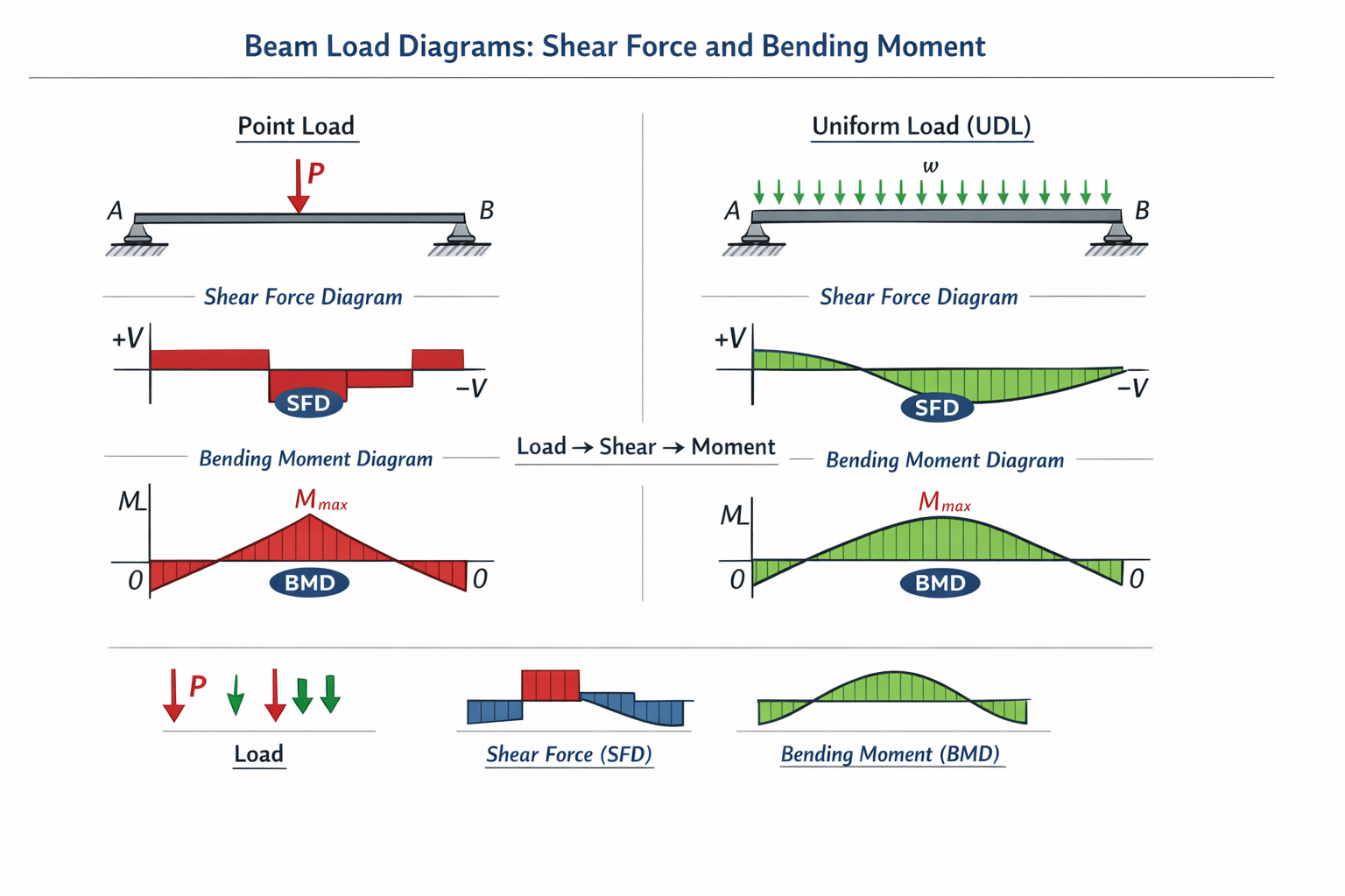
Beam load diagrams translate numerical results into a visual form that shows how a beam actually responds along its span. The two most common diagrams are the Shear Force Diagram (SFD) and the Bending Moment Diagram (BMD). Both are drawn along the beam length, from the left support to the right support.
Shear Force Diagram (SFD)
The shear force diagram plots internal vertical forces at every point along the beam.
For a point load, the shear force remains constant between supports and changes suddenly at the load location. That sudden jump equals the magnitude of the point load.
For a uniformly distributed load (UDL), the shear force changes gradually, forming a straight sloping line because the load is spread continuously along the beam.
A sign change in the shear force often marks a location where bending behavior shifts, which is useful when checking critical sections.
Bending Moment Diagram (BMD)
The bending moment diagram shows how bending stress develops along the beam.
Under a central point load on a simply supported beam, the bending moment diagram forms a triangle, with zero moment at the supports and a maximum value at midspan.
Under a full-span UDL, the diagram becomes a smooth curve (parabolic), again reaching its peak at midspan.
The maximum bending moment from this diagram is used later to check whether the selected beam section can safely resist bending stress.
Visual Relationship Between Load, Shear, and Moment
Load, shear, and bending moment are directly connected:
- The slope of the bending moment diagram equals the shear force.
- The slope of the shear force diagram equals the applied load intensity.
This relationship explains why a constant shear produces a straight-line bending moment, while a varying shear produces a curved bending moment.
Practical Examples
Example 1: Point Load
A simply supported beam spans 5 m with a 10 kN point load applied at midspan.
- Support reactions: 5 kN at each end
- Shear force: +5 kN from the left support to midspan, then −5 kN to the right support
- Maximum bending moment: 12.5 kN·m at midspan
The SFD shows a sudden drop at the load position. The BMD peaks exactly where the load is applied.
Example 2: Uniformly Distributed Load
A simply supported beam spans 4 m with a UDL of 2 kN/m over the full length.
- Total load: 8 kN
- Support reactions: 4 kN at each end
- Maximum bending moment: 4 kN·m at midspan
The shear diagram slopes linearly from +4 kN to −4 kN, while the bending moment diagram forms a smooth curve.
Steps to Use the Calculator for Diagrams (Accurate to This Tool)
- Select the unit system (metric or imperial) and keep all inputs consistent.
- Enter the beam length (clear span between supports).
- Choose the load type:
- Point Load → enter load magnitude and its position from the left support.
- Uniformly Distributed Load (UDL) → enter load magnitude per unit length.
- Enter material properties (E and I) if deflection results are required.
- Click Calculate to obtain numerical results for shear force, bending moment, deflection, and support reactions.
The calculator outputs maximum values numerically. Diagrams are interpreted conceptually from these results rather than drawn graphically.
Privacy, Data Handling, and Security
Reputable online beam load calculators process calculations locally within your web browser or via a secure server without storing personal information or project details. Input values are typically not logged to a database or linked to user identities. For maximum privacy, use calculators that explicitly state no data tracking or choose offline software tools. Users concerned with data security should avoid inputting any sensitive, project-identifiable information into these tools and clear their browser cache after use.
Frequently Asked Questions
What is the difference between load calculation and load capacity?
Load calculation determines the forces (demand) applied to a structure. Load capacity is the maximum force a specific structural element can safely resist (supply). Design ensures capacity exceeds demand with an appropriate safety margin.
Do these calculators include safety factors?
Most basic online calculators do not apply the safety or load factors mandated by building codes like IS, Eurocode, or AISC. They output nominal service loads. A structural engineer must apply the relevant factors from the governing code to determine design loads.
Which building codes does the calculator follow?
Generic calculators do not follow any specific building code. They apply universal principles of statics. Code compliance is the responsibility of the engineer who interprets the results and applies code-prescribed load combinations, material factors, and design equations.
Can I use these results for building permit approval?
No. Permit applications require stamped calculations and drawings prepared by a licensed professional engineer. Calculator results are suitable for preliminary planning and educational purposes only, not for official submission.
Are results in metric or imperial units more accurate?
Accuracy depends solely on consistent unit usage, not the system itself. The calculator is only as accurate as the inputs provided. Errors from unit confusion are more common than calculation inaccuracy.
When must I consult a structural engineer?
Consult a licensed structural engineer for any permanent construction, load-bearing wall modifications, unusual loading conditions, or when final design and code compliance are required. Their expertise is essential for addressing constructability, material selection, connection design, and site-specific challenges.
Where does the maximum bending moment occur?
For a simply supported beam, the maximum bending moment occurs where the shear force crosses zero. With symmetric loading, this is usually at midspan.
Why does a UDL create a curved bending moment diagram?
A UDL causes shear force to change continuously along the beam. Since bending moment is the integral of shear force, the result is a curved (parabolic) diagram.
Can shear force be zero while bending moment is not?
Yes. At the location of maximum bending moment, shear force is zero, but bending moment reaches its highest value.
Disclaimer: This content is for informational purposes only. Beam load calculators provide approximate results for educational and preliminary planning. Structural design must be performed by a qualified professional in accordance with all applicable local building codes and regulations. The authors and publishers assume no liability for any design decisions made based on calculator outputs.